Tutorial Module02 Draft
Mesh Creation
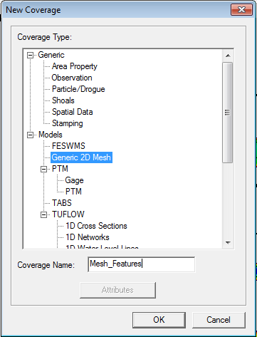
Now that the required datasets are loaded we can begin to create the model mesh. We need to create a new coverage in the map module. Right click on the “Map Data” heading and select “New Coverage” as shown below. The coverage type should be set to Models >> Generic 2D Mesh. Name the coverage “Mesh_Features” and then select OK.
Make sure the newly create “Mesh_Features” layers is selected in the table of contents as per the image below.
In this layer we need to create a feature arc (polyline) in SMS to define our model extent. In the majority of cases this can be done using the create feature arc button (![]() ). For this tutorial however, the model we are going to create covers the full extent of our bathymetry scatter dataset. We can use the extent of the bathymetry dataset to define our model extent. This is done by converting the data on the scatter dataset into an object in our “Mesh_Features” layer. To do this right click on the RiverBend_Bathymetry scatter dataset and the select convert >> Scatter Boundary >> Map.
). For this tutorial however, the model we are going to create covers the full extent of our bathymetry scatter dataset. We can use the extent of the bathymetry dataset to define our model extent. This is done by converting the data on the scatter dataset into an object in our “Mesh_Features” layer. To do this right click on the RiverBend_Bathymetry scatter dataset and the select convert >> Scatter Boundary >> Map.
After the conversion, the scatter dataset boundary should be in the Mesh_Features layer (this is easier to see with the scatter set turned off). This is shown in the image below.
Zoom in to the northern boundary of the model, and select the two corner vertices (![]() ) and convert these to nodes.
) and convert these to nodes.
Select the feature arc (![]() ) and then right click and use the redistribute vertices to redistribute 10 vertices along the line.
) and then right click and use the redistribute vertices to redistribute 10 vertices along the line.
Repeat the process at the southern edge of the model.
Note: In later SMS versions, a node may be created automatically at the southern edge of the model. In that case, select the node (![]() ) and convert it to a vertex before redistributing vertices.
) and convert it to a vertex before redistributing vertices.
Select the two feature arcs along the banks of the river and redistribute with a specified spacing of 20 (metres). The SMS window should now appear as below.
In order to build a mesh, we need to create a polygon from the feature arcs. To do this, select Feature Objects >> Build Polygons.
Using the polygon select tool (![]() ), select the polygon which has been created from the feature arcs. The default mesh type is paving, using this mesh type, the default elements are triangles as per the image below.
), select the polygon which has been created from the feature arcs. The default mesh type is paving, using this mesh type, the default elements are triangles as per the image below.
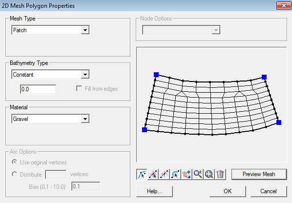
The mesh type patch uses quadrilateral elements preferentially. Change the mesh type to “Patch” and select Preview Mesh. With the entire section of river as a single patch mesh, the quadrilateral elements get wrapped around the bend as shown in the image below:
Note: You may receive an error about overlapping elements
To avoid this, it is best to include sections across the channel (perpendicular to flow) at regular spacing along the channel, and in particularly around the bends.
To do this use the create feature arc button (![]() ) to create the lines across the river. These do not need to snap to existing vertices, new ones will be created if required. An example is shown below, once the lines are drawn, 10 vertices should be distributed along each arc. Using the select tool, multiple arcs can be selected holding down shift.
) to create the lines across the river. These do not need to snap to existing vertices, new ones will be created if required. An example is shown below, once the lines are drawn, 10 vertices should be distributed along each arc. Using the select tool, multiple arcs can be selected holding down shift.
Once the additional arcs have been created, the polygons need to be rebuilt. To do this select Features Objects >> Build Polygons from the menu. Once rebuilt, the individual polygons can be selected and have different mesh types applied. Select the southernmost polygon and select attributes (or double click on the polygon). Ensure the Mesh Type is set to patch and then hit preview mesh.
In the mesh preview window, the mesh is now much better aligned with the predominant flow direction than previously. However, along one bank there are more vertices than the other; TUFLOW FV can handle both triangles and quadrilateral elements, so this is not a major issue. However, to align the elements with the flow direction, quadrilaterals are preferred over triangles (small elements, such as triangles in deep water can also reduce the timestep).
In this scenario, the river width remains relatively constant and we will use quadrilateral elements throughout the mesh. To achieve this, in the mesh properties dialogue, select the two bank lines and then in the Arc options the number of vertices can be redistributed. If both are selected, each bank will have the same number of vertices and quadrilateral elements will be created.
Repeat the process along the channel, an example is shown below.
When you have finished creating you mesh areas, we need to specify an elevation data source. This can be done individually for each polygon, however, as the bathymetry source is consistent, we can select all polygons using the polygon select tool (![]() ) you can drag and drop a box around all polygons. With all the polygons selected, right click and select “Attributes”.
) you can drag and drop a box around all polygons. With all the polygons selected, right click and select “Attributes”.
In the prompt, tick the check box next to Bathymetry type and the select “Scatter Set”. Once selected, hit the “Scatter Options” button. In the Scatter options set the Interpolation method to Linear and the extrapolation to “Single Value” and enter a value of 2.
When SMS has reshaped the vertices along the edge of the model it is possible that some are just outside the bathymetry dataset. The extrapolation method defines how these are set, we have used a high elevation, and alternative option is to use the Inverse Distance Weighting option.


